how do you get inj duty?

CruiseGTi-R

Member
How do you work out your injector duty?

My data logger can pick up the speed sensor frequencies to each injector, but I'm not sure whether this is any use :oops:.

How are injectors controlled?


Cheers, toby
 
A

AJ4

Guest
Not an easy one to explain really unless you understand the term 'duty cycle'...

The duty cycle is the amount of time a signal spends at max voltage, expressed as a percentage. Suppose you have a 12 v system, if it was always at 0v it would have a duty of 0%, always at 12v it would be 100%, switching rapidly between the two with equal on/off time would be 50%.

_____________________ = 0%


_||_||_||_||_||_||_||_||_||_ = 30%


_| |_| |_| |_| |_| |_| |_| |_ = 50 %


.| |.| |.| |.| |.| |.| |. = 80%

_____________________
= 100 %

Hope that makes sense :D

Measuring duty cycle is very easy as your only comparing the 'on' time to the 'off' time, but injector duty cycle on engines is different. There are two systems in place that make them work. Initially there is a high pulse that opens the injector, that kind of 'gets it going', which is then followed by lower level pulses which 'keep' it going. Note that the frequency should never change, just the width of the pulses.

Depending on what measurement gear you have, it could be measuring the 'opening' pulse or the 'keep going' pulse, both of which will give different values... The best way to see it is on an oscilloscope :(

I'm working on a circuit that differentiates the injector pulses so that it can be measured accurately electronically, but if you just want a quick measure you can use a DC ( analogue / moving coil ) meter.

Set the meter up so that the needle is on 0 at 0volts and 10 ( full scale ) at 12v ( or whatever the injector pulse voltage is ). The needle should now roughly indicate what your injector duty cycle is. It has to be a fast moving needle though and it'll flicker like hell, but its a good indication.
 
Last edited by a moderator:

CruiseGTi-R

Member
ok, this is good stuff.

I've a data logger which taps off the ecu. It can read speed signals, so I picked off inj 1,2,3,4 speed signals.

Thing is they're listed in the ecu pin read out as engine speed signals, so I'm not sure what they do, why there is one for each injector.

The signals of all 4 injectors are frequencies, but they start at around 7Hz at idle and go up to 40Hz flat out.

I think they're not what I need?
 
A

AJ4

Guest
balls, the diagram didn't come out too well :D

it sounds like thats the signals you need, but its not the frequency your interested in. Depends on how fast your measurement system is, it could pick up the peak on one pulse and then the next time it takes a sample there has already been a few pulses in between, in which case it will read the wrong frequency.

you really need to see it graphically, is there any way you can record voltage versus time and then plot it ?

maybe this will help to understand - http://en.wikipedia.org/wiki/Duty_cycle

remember, its not the frequency thats changing, but the duty cycle ( on/off time ). If your equipment is reading different values then its because of its sample period wrongly coinciding with peaks / troughs at random.
 
Last edited by a moderator:

CruiseGTi-R

Member
I can plot the frequencies vs time vs any other parameter (revs, maf etc).

But how do I plot voltage (voltage from what)?

The inj frequencies are very smooth in transition, but interestingly just now and again it'll jump. Say as passing 35Hz it'll suddenly flicker to 180Hz or something, then go back to being smooth. Being mostly smooth do you think its reading the lower level pulse freqencies ok?

Although it doesn't explain why they change values.

The 4 inj signals from the ecu (from memory pin 101, 103 etc) are all listed as 'engine speed signal sensor'. Maybe this isn't the actual pulse frequencies you refer to, but merely engine speed which the ecu uses to do something with the injectors?

Having said all that, when I tap into the ecu pin which is listed as engine speed signal sensor (actual RPM) the frequencies are much higher.

Does PFC Pro or other management tap into pins 101, 103 etc?
 
A

AJ4

Guest
I'm not sure your measuring the right thing. The injectors are rapidly switched on/off/on/off to control fuel, so the control signal is a square wave. There shouldn't be any change in frequency. The only thing that changes is the width of the pulse.

This is what the signal should look like -


What you really need to do is to plot voltage versus time on those injector pins ( 101, 103, 110, 112 ? ) so you get a diagram like the one above. The actual freuquency is irrelevant, only the ratio of on time to off time ( duty cycle ).
 

CruiseGTi-R

Member
Those four injector pins are 'engine speed sensor signal' rather than an analog voltage signal. So I've used the 'speed signal' inputs on my data logger. I haven't tried to tap a voltage from them, you reckon those pins will give a voltage like you describe above?

They also vary as rpm climbs, so I think they are as described, just related to engine speed, god knows what the ecu/injectors does with this signal?

Anyway if they give a voltage I've a free analog input to use, but these are capped at 5V (and give warning not to exceed it). I think speed related signals go up to 25V???

How does everyone else determine their inj duty, lots of people quote their's?

I'm shit at this stuff, you've been a big help Ross.
 
Last edited:
A

AJ4

Guest
I think your being confused because your making the wrong kind of measurement and getting strange results. Heres how the injectors work -

There is a common 12 volt supply that goes to the injectors. There is a resistor in series with the injector to limit the current. The return path after the injector goes back to the ECU. The ECU switches the lines between ground and 12v, which in turn allows current to flow through the injector or not.

Suppose the fuel supply could flow 1 litre per minute. If the injector was switched on totally ( had a constant supply of 12 v ), then 1 litre per minute would flow.

If the injector was rapidly switched on and off at an equal rate, then only 0.5 litres per minute would flow.

Suppose you switched the injector on for 1 second, then off for 3 seconds and repeated this rapidly, the on to off ratio would be 1:4 or 25% ( this means that the injector is only switched on for 25% of the time ). In this case the fuel flow would be 0.25 litres. This is how the duty cycle controls fuel rate. 100% and maximum fuel flows, 50% and half flows, 0% and none flows.

As for frequency, it doesn't matter, it can be anything. If you switched the injectors at 1 second on and 3 seconds off you would get the same fuel flow ( 25% ) as switching them at 0.1 seconds on and 0.3 seconds off ( still 25% ). It the average amount of time that determines the fuel flow, not the frequency.

The signals that you see on the ECU should be a switching DC voltage that switches rapidly between 0v and 12V. The actual speed it switches is unimportant, its the ratio of time@0V to time@12V that is.

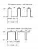
You need specialised equipment to measure duty cycle, you can't measure it with a multimeter. Ideally you need an oscilloscope or a means of plotting the voltage versus time ( like the image above ).

I'll try and explain why frequency is unimportant and why your getting bad results. Frequency is measured by detecting a rising voltage and then waiting until the voltage drops and starts to rise again ( 1 complete cycle ). The time it takes to complete one cycle is measured and divided into 1 to give the frequency ( number of cycles per second )

Suppose it takes 0.25 seconds to complete one cycle. This gives a frequency of 1 second / 0.25 seconds = 4 Hz ( 4 cycles per second ).

Suppose you have an injector pulse that is switched on for 50% of the time ( 50% fuel flow ), and each pulse is 0.125 seconds on and 0.125 seconds off. One complete cycle would take 0.25 seconds which is 4 cycles per second ( 4 Hz ).

Suppose now the injector duty cycle is changed from 50% to 75% which gives 75% fuel flow. The injector is switched on for 0.1875 seconds and off for 0.0625 seconds. It still takes 0.25 seconds for one complete cycle ( 4 Hz ) but the fuel flow is 25% more.

It can be 1 cycle per second or 1 million cycles per second, if the on/off ratio ( duty cycle ) is the same, the same amount of fuel will flow.

The problem your having is with your test equipment. To measure frequency, you need to have some sort of repeating pattern to measure. As the injector pulse is varying, the positive and negative going slopes ( needed to measure frequency ) are all over the place. As the duty cycle varies, the pulse width varies and the edges of the pulses are zooming into each other and out again. A frequency counter will just try to 'best guess' what the frequency is. How frequency is measured is pretty complicated anyway, and best we don't start on that one :D

Trust me though, you should be looking at a DC signal that switches between ground and 12 Volts on those ECU pins, nothing else.
 
A

AJ4

Guest
I did a piccy of the type of signal you are looking for. Its actually in reverse as the injector is on at 0V and off at 12V because the ground is switched and not the positive, but you get the idea.
 

Attachments

Top